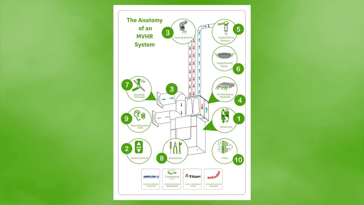
The Anatomy of an MVHR System
(The Ultimate Beginner’s Guide to MVHR)
As energy efficiency and indoor air quality become increasingly important considerations in building design, Mechanical Ventilation with Heat Recovery (MVHR) systems have gained in popularity. MVHR systems play a crucial role in maintaining a comfortable and healthy indoor environment whilst minimising energy consumption. Here we delve into the anatomy of an MVHR system, explaining how the key components of an MVHR system work.
(1) The MVHR Unit: How does it work and why you need a professional design before you start?
The MVHR unit is the heart of the system. It runs 24/7/365 removing stale air and introduces fresh air, ensuring the house is always well ventilated. It works by extracting stale, humid air from the wet rooms (bathroom, kitchen, utility, etc.) and passing it through a heat exchanger – where it recovers around 80-90% of the heat from the extracted air. This heat is then used to warm the air which has been drawn into the living areas of the home (bedrooms, living rooms, dining rooms, studies). The use of MVHR has increased massively in recent years due to the building of new homes with increasing levels of insulation and air tightness.
An MVHR system is an essential part of a modern house and a good, well-designed system ensures it is tailored to meet the specific ventilation needs of your home. The first thing therefore is to commission a professional MVHR Design. This is important because it ensures that the system is efficient and effective. A good design will factor in key considerations such as:
- the size of your home
- the number of occupants and number of rooms
- how the duct runs (pipes) will flow through the structure of the building
- where the valves should be placed to ensure the most effective air flows
From this information, the design will be used to determine ‘System Pressure’ which is a factor of duct type, duct route and duct length. Duct pressure has a massive impact on how much air a unit can move so it’s essential to have a system design completed prior to selecting your MVHR unit to avoid under sizing the unit. When selecting the unit, the designer will seek to have the low speed running at c.65% of the full motor capacity. This is the optimum setting to reduce wear and stress on the motor and prolong the life of the unit.
(2 & 3) Ducting

 |
 |
Terminations to atmosphere:
MVHR ducting between the unit and to/from the atmosphere must be insulated to prevent condensation and reduce heat loss. The insulation should have a thermal resistance (R-value) of at least 0.625 m²K/W. This is typically achieved with a minimum of 25mm of insulating material that has a thermal conductivity (k-value) of 0.04 W/mK or less (eg, foil-faced mineral wool wrap).
Enhanced Standard: In very cold climates or for Passivhaus projects, 50mm to 100mm of
insulation is recommended.
Vapour Barrier: The insulation material should be vapour-proof to prevent
moisture from the surrounding air from entering the insulation and
reducing its effectiveness.
Duct Type: Use smooth, rigid ducting for the main runs i.e insulated steel, as it is
efficient and easier to seal and insulate. Pre-insulated rigid ducting (like EPP or EPE) is also
an excellent option.
Sealing: All joints must be thoroughly sealed to prevent air leakage. This can involve using glue, screws, and airtight tape.
For the final run to the external atmosphere, ensure the duct is well-supported and any
penetration through the building fabric is sealed to maintain the building's airtightness and moisture barrier.

(4) Manifolds

Manifolds are used with radial ducting systems. Loosely explained, they are ‘air reservoirs’ that are placed between the MVHR unit and the rooms. Manifolds will be connected to one main duct then a network of ducts will be connected to each room. On the ‘room side’ of the manifold there are generally between 4 - 12 ports (feeding 4 – 12 duct runs/rooms) and, whilst some have more, a typical system would have two manifolds - one for the supply air and one for the extract air.
For some installations, a noise attenuator is also used. Attenuators are designed to reduce the transmission of noise through the ductwork, either from equipment into occupied spaces or between occupied spaces.
(5) Plenums

At the end of each duct run, a plenum is connected. These can be placed in either the walls, floors or, most commonly, ceilings. One end connects to the duct run, the other points into the room and has a valve attached.
(6) Valves

Valves play a critical role in the performance of an MVHR system as they control the air flow into each room. This is essential as, when the system was originally designed, each room will have had a specified air flow rate set. Once the system is installed the unit will be commissioned and the valves adjusted to match the air flows specified at the design stage. This is important as Building Regulations require that the actual air flow rates match those that were specified at design. Should a discrepancy between design and actual rates be found, it is likely to cause an issue with Building Control.
Apart from their essential function as air flow regulators, valves have an aesthetic effect on the room. There is a wide variety of valves from basic in/out valves to specific supply or extract models. They may also include flow directors to move the air in a specific direction which helps increase efficiency of the unit and allow for short duct runs which will help control costs.
(7) Extract/Supply Terminals

Extract/supply terminals can be located on roof or wall locations. At the design stage, roof terminal location and roof type are reviewed to ensure the correct roof terminations and materials are selected. A further important consideration is the duct diameter, as this will need to be matched to the airflow of the unit.
(8) Accessories
Accessories encompass additional components that enhance the functionality or aid the installation of the MVHR system. This may include filters to improve air quality, insulation, foil sealant tape, sensors for monitoring and control, and other supplementary items to assist with installation.
(9) Noise-Attenuation
(10) Filters
(11) MVHR System Controls

Most MVHR units are fully automated meaning that once set, there is no need for regular changes to the settings. There are however a range of additional controllers that can be used from simple room-based boost switches, controls showing filter change alerts and running mode to manufacturer based Apps that allow remote control. Typically, there are automated demand control functions which use sensors to increase speed and performance relative to the amount of CO2, temperature or humidity levels.
Ready to start your MVHR project but still have questions? Give us our UK-based experts a call on 01892 600121 or email mvhr@epicair.co.uk and we can answer your MVHR questions and create the essential and important designs you'll need before you get going.


